To all engineers and technicians out there: Beware of old gear that appears to be in working condition! Last year, a friend dropped off an Electro-Harmonix Mike Matthews Dirt Road Special here. It was actually working but there was extreme crackling noise in the volume pot. I was thoroughly impressed by the sound of the built-in "Small Stone Phaser". The label on the highly regarded British made Celestion Speaker was visible through a bass port on the back panel. Here are some pictures of the amplifier.
 |
| Electro-Harmonix Mike Matthews Dirt Road Special |
 |
| Top view |
To clean the pots, all of which were quite noisy, I decided to remove the back panel and take a look inside. This is when things began to get interesting. I had noticed that the Philips screw fastener heads visible on the exterior were considerably rusty. However, I was surprised to find that the three wood screws along the bottom edge of the back panel were securely rusted into the wood. One of the three would not even begin to turn. I gently tapped on each of them with a Philips driver bit and eventually removed two of them but the third did not respond. Finally, after stripping the screw head, I had to drill the head of the screw away so that only the shaft remained. Then I could remove the back panel. Here are all of the wood screws and a couple of machine screws removed later.
 |
| Rusted screw fasteners |
What I noticed right away was that the amp must have been in a flood because, not only were the screws rusted but also the back of the speaker was rusted with much of the paint flaking away.
Anyway, the pot interiors were accessible for spraying with contact cleaner without any further disassembly. With the pots cleaned, I applied power and there was no sound at all from the speaker! I unsoldered one of the speaker terminals and found that the speaker's impedance was an open circuit! Next, I removed the speaker and installed another twelve inch speaker. There was a steady hum from the amplifier but otherwise no sound! After finding a schematic of the output circuit online, the next thing I did was to remove the amplifier chassis, unsolder the two power output transistors and find that the PNP transistor (TO3 case) had a collector-to-emitter short. The NPN transistor pn juncitons tested fine with no shorts. Here is a photo with the PNP transistor removed:
 |
| PNP Transistor removed |
Here is another close-up of the board for reference.
 |
| Printed on the board is the number EH1313 B |
I tried checking the connections to the speaker's voice coil and could find nothing amiss. I finally decided to remove the cone/surround/spider/voice coil assembly to try to get a look at the voice coil because it appeared that the coil wire must have parted somewhere in the coil. In addition, the coil was rubbing against something in the gap and not moving freely. With the cone assembly removed from the basket, I noticed that there was really heavy rusting around the spider edge and the spider glue had disintegrated into small fragments, some of which had fallen into the voice coil gap.
 |
| Rusting on speaker basket |
 |
| Rust and glue particles in voice coil gap |
At some point, with the cone assembly removed, I measured a voice coil DC impedance of 7.2 Ohm. This was surprising. I decided to reinstall the cone assembly after cleaning the rust and clearing the debris from the voice coil gap.
Close examination of the voice coil showed a little scraping but did not reveal any obvious broken wire in the coil.
 |
| Scraping on voice coil |
 |
| Scraping on voice coil |
After thorough cleaning with vacuum and fine tweezers, I temporarily covered the gap with black electrical tape to keep filings from entering the gap while cleaning loose rust away.
 |
| Loose rust cleaned away |
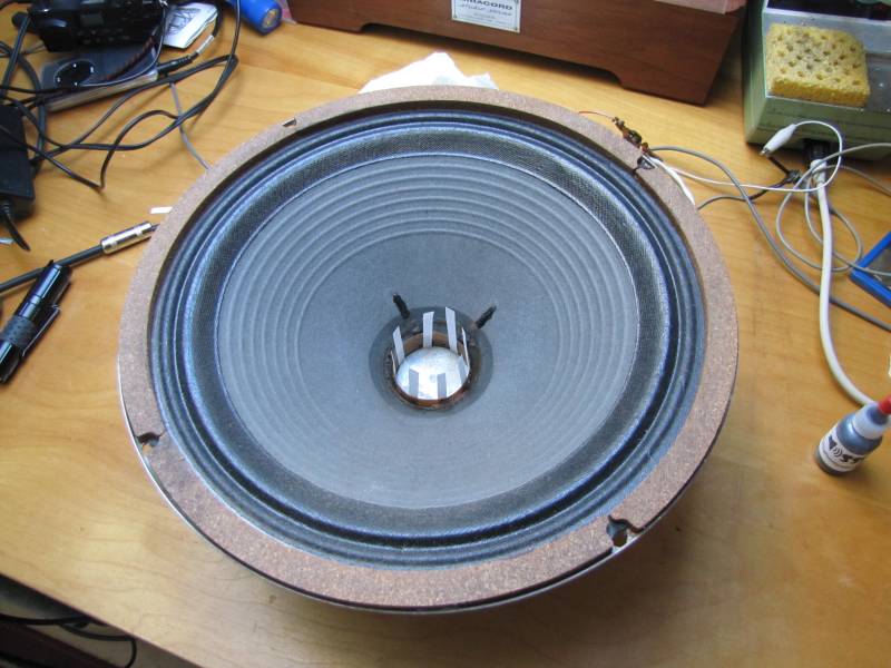
With the rust cleaned out, it was possible to reinstall the cone assembly and align the coil in the gap.
 |
| Speaker cone assembly glued and aligned with paper strips |
 |
| Close-up |
However, after the glue set, the voice coil had opened up again and the carefully restored speaker did not work! Here is a picture of the setup showing a voice coil open circuit on the meter.
 |
| Speaker still does not work! |
The only way I could get the open voice coil to close was to insert a short wood brace across the diameter of the coil former. As soon as I discovered this, I positioned the brace for maximum effect and glued the ends to the former. Here is a photo showing the speaker working with an AC voltage applied to the terminals.
 |
| Celestion speaker temporary repair with wood brace |
With the speaker working, if only temporarily, I decided to order a matched PNP-NPN transistor pair to replace both output transistors. I selected transistors with robust specifications, including maximum ratings not likely to be exceeded in this amplifier design.
Here is a picture with the new transistors installed.
 |
| Amp with new output transistors installed |
I powered this up using a Variac autotransformer. Everything is working fine with the Variac high enough to make 14 Volts DC from the power supply. With a full 120 VAC applied, the power supply voltage would be much higher at about 70 Volts. My friend is suggesting that his potential customer might be interested in doing some studio work with this amp. If that is the case, I may decide to change the power transformer to one with 12 VAC or even 9 VAC secondary to reduce the power and protect the original speaker, as repaired, from too much power from the amp. This amp is really loud with only 14 Volts. In the event someone installs a new speaker, the original transformer should be used. On the other hand, the amp should work great powered with a 12Volt car battery instead of the AC power supply! I will post further photos soon...
For more on this, check out the latest post at
EH is back for repairs.


")